NEMA Wiring Diagram Guide for Electrical Specialists
Approximately seventy percent of the electrical failures within establishments stem from inadequate wiring techniques. These figures accentuates the need of following recognized protocols, highlighting NEMA wiring diagrams’ value for electrical experts. Through these drawings, wiring arrangements that fulfill both performance productivity and optimal security standards are presented.
The objective of this manual is to provide electrical practitioners with profound understanding into NEMA standards. Highlighting the significance of proper electrical installations is essential. Through mastering these rules, technicians can drastically minimize the likelihood of hazards and guarantee they meet safety standards supported by Installation Parts Supply. Knowledge in l 14-30 plug is crucial whether designing novel systems or repairing existing ones, as it improves the capacity to offer reliable and consistent electrical answers.
Summary Highlights
- NEMA wiring schematics are essential for guaranteeing electrical safety and compliance.
- Correct wiring techniques can decrease electrical malfunctions substantially.
- Grasping NEMA standards improves the effectiveness of electrical arrangements.
- Installation Parts Supply supports following safety protocols in electrical tasks.
- NEMA schematics accommodate a wide range of uses across various fields.
Comprehending NEMA Standards and Their Significance
NEMA standards are crucial in the electrical sector, guiding security and functionality meticulously. Developed by the National Electrical Manufacturers Association, they establish key standards for developing, examining, and marking electrical equipment. This ensures consistency and trustworthiness across all electrical set-ups, which is priceless.
What Are NEMA Standards?
NEMA classifications vary from grades 1 up to 13. Each level defines the criteria required for electrical devices to perform optimally. For example, NEMA 1 provides minimal indoor protection but is missing dust shielding. On the other hand, NEMA 4 guarantees devices is sealed, a requirement for enduring substantial water contact. Grasping these classifications is essential in picking proper devices.
Why NEMA Criteria Matter for Electrical Security
The function of NEMA norms in guaranteeing electrical safety is substantial. They contribute greatly in minimizing electrocution risks, device malfunctions, and burn risks. Accurate adherence to NEMA standards allows equipment to operate securely under particular environmental conditions. For outdoor usage, NEMA 3 ratings offer protection against the weather, guarding the device from inclement weather like precipitation and snowfall. In regions prone to explosions, standards including NEMA 7, 8, and 9 are vital for ensuring safety.
Uses of NEMA Criteria in Wiring Drawings
The application of NEMA norms in wiring diagrams is vital for protected, optimal electrical installations. These diagrams make use of uniform symbols and formats based on NEMA classifications, streamlining the understanding of detailed electrical setups. This uniformity is beneficial. It fosters transparency, standardization, and reduces errors, thus improving electrical security across residential and factory sectors.
NEMA Wiring Diagram Essentials
NEMA wiring diagrams are crucial for electrical specialists, making complex linkages unambiguous. They outline the junctions and parts in different installations. By grasping the parts, types, and notations of NEMA diagrams, electricians can enhance their operations in installations and maintenance.
Elements of NEMA Wiring Diagrams
NEMA drawings include key parts for distinct electrical configurations. You’ll discover wiring endpoints, connectors, and additional equipment for safe connections. Every piece secures energy is spread efficiently, in accordance with safety guidelines.
Varieties of NEMA Wiring Drawings
NEMA utilizes various diagrams, like linkage schematics and circuit designs. Schematics detail device interconnections, while designs illustrate energy distribution. Choosing the right schematic helps with problem solving and installation.
Typical Icons Employed in NEMA Wiring Schematics
Symbols in wiring drawings are vital for clear conveyance. They illustrate switches, networks, and connectors. Understanding these notations aids groups comprehend schematics properly. Such practice ensures setups adhere to NEMA standards.
NEMA Wiring Schematic Attributes
For electrical experts, comprehending the key components of accurate electrical wiring diagrams is essential. These diagrams bring both transparency and completeness, aligning configurations with NEMA criteria. They necessitate exact labeling and proportioning to curtail installation errors. This encourages a protected and optimal workplace.
Essential Characteristics of Correct Electrical Wiring Diagrams
Accurate electrical wiring schematics are vital in electrical undertakings. They incorporate important qualities such as:
- Clarity: Drawings must be unambiguous, reducing the risk of misinterpretation.
- Completeness: They need to contain all key parts, connections, and electrical standards.
- Standard Compliance: Following NEMA standards is mandatory for ensuring security and performance.
- Detailed Labeling: Distinct markings on each part are crucial for comprehension and error prevention.
- Correct Scaling: The scales should mirror the actual setup to represent the arrangement accurately.
Comprehending NEMA Coupler Pinout
Understanding of NEMA coupler configuration is crucial for making proper connections in electrical systems. Awareness of distinct pin arrangements upholds safety and equipment operation. There is a range of NEMA connectors, designed for distinct voltages and flows, encompassing:
| Connector Model | Current Rating | Voltage Level |
|---|---|---|
| L5-15 | 15A | 125V |
| L5-20 | 20A | 125V |
| L14-20 | 20A | 125/250V |
| L1430C | 30A | 125/250V |
| L620C | 20A | 250V |
| L1430C | 30A | 125/250V |
| L630R | 30A | 250V |
Grasping NEMA coupler configurations is vital for stable connections, boosting effectiveness. It’s imperative to pair connectors with devices properly using locking or flat blade variants, to avoid dangers.
NEMA Device Wiring
NEMA appliance wiring covers various configurations for secure electrical appliance linkages. These guidelines ensure that equipment integrate securely, minimizing danger. Knowing the different NEMA appliances and their wiring is crucial for technicians.
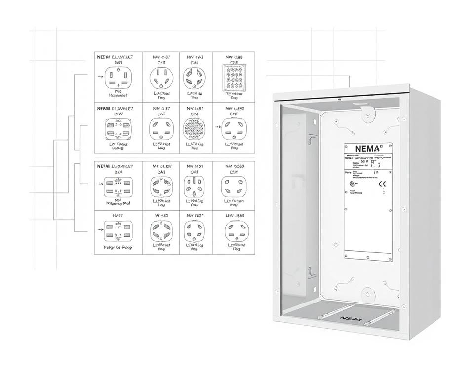
Various Types of NEMA Appliances
NEMA classifies units by type based on voltage levels and flow demands. Key configurations are:
- 2-Pole 2-Wire
- 2-Pole 3-Wire Grounding
- 3-Pole 3-Wire
- 3-Pole 4-Wire Grounding
- 4-Pole 4-Wire
- 4-Pole 5-Wire Grounding
These arrangements are employed in domestic settings and factories, operating at 125V, 208V, and 480V.
NEMA Outlet Wiring Demystified
NEMA plug wiring varies to suit diverse power needs, with locking types ensuring secure junctions in vibrating settings. For example, the L5-15 plug is rated for 15 amperes, frequently used in enterprise settings, whereas the L14-20 is designed for 20 amperes at 125/250 voltage.
The NEMA designation system helps in choosing the right plugs, emphasizing characteristics like polarity and grounding. This precision guarantees that devices function safely.
NEMA Outlet Wiring Standards
Accurate wiring of NEMA receptacles aligns with electrical standards and safety norms. Such as, L530R receptacles should be wired for 30 amps at 125 voltage, with L630R variants for 250 voltage. Proper grounding is crucial to dodge electrical accidents.
Choosing approved NEMA plugs and receptacles guarantees protected, regulation-compliant setups. It’s critical to consult official guidelines when setting up.
NEMA Motor Wiring and Uses
NEMA motor wiring is vital in electrical design, notably for industrial use. Knowing how NEMA motor setup works secures that machines are set up for optimal performance. Motors, like single-phase and three-phase models, need accurate wiring to operate securely and optimally.
Overview of NEMA Motor Wiring
Understanding NEMA motor wiring demands understanding of linkages and configurations. Most three-phase motors offer dual-voltage, meaning they can operate at both low (208-230V) and high voltage levels (460V). Wiring at high voltage allows motors to draw less current than at low voltage. High voltage advantages comprise smaller wires for the power feed, a notable benefit for motors exceeding 10 HP.
While both NEMA and IEC appliances are used in the industry, NEMA variants are usually larger and more expensive than IEC ones for less than 100 HP applications. NEMA controllers span size 00 to 9, appropriate for various uses. A standard feature in NEMA starters is a Fault Class of 20, designed to activate when a motor’s current surpasses 6-fold the rated current in 10 seconds.
Opting for the Right NEMA Motor Configuration
Selecting the appropriate NEMA motor arrangement impacts overall performance and safety. A common three-wire control circuit utilizes three wires for a start/stop pushbutton interface, facilitating simple motor operation. Frequent three-phase setups include the 12 Lead Dual Voltage and 6 Lead, supporting Wye and Delta configurations.
IEC motor starters commonly feature phase failure detection, boosting safety. They also include modifiable Trip Ratings for tailored protection in low voltage levels operations. Moreover, many models have heat protection, critical for single-phase and Dual Voltage configurations.
| Arrangement | Power Type | Current Specification | Usual Function |
|---|---|---|---|
| 12 Lead Dual Voltage | Dual Voltage (208-230V / 460V) | Motor size dependent | Wye Start – Delta Run applications |
| 6 Lead | One or Dual Voltage | Maximum 32A | Both Wye and Delta arrangements |
| Single Phase | Single-level Voltage | Varies (1-5 amps adjustment) | Two Speed, Two Winding applications |
| Delta Connection | High-Power Voltage | Depending on setup | Various applications including Current Transformers |
In Closing
Comprehending NEMA wiring schematics and norms is vital for electrical experts looking to boost their expertise and comply with electrical safety standards. These principles not only ensure safe and high-performing electrical installations but also prevent risks associated with incorrect wiring. As mentioned, adhering to NEMA criteria yields the enhanced performance of multiple NEMA devices and configurations.
For electricians, the selection of superior supplies can greatly affect the success of their projects. Installation Parts Supply offers a vast selection of wiring supplies aligned with NEMA criteria. This allows experts to get essential components for complying with these important regulations. High-quality resources and profound understanding of NEMA wiring diagrams substantially improve project protection and effectiveness.
During electrical deployments, always place safety and precision as a priority. Mastering NEMA norms provides the insight necessary for implementing industry standards precisely. This secures that every electrical link formed conforms to superior norms.
Common Questions
What are NEMA wiring schematics?
NEMA wiring drawings illustrate the configurations and junctions of NEMA-standard electrical devices. They adhere to safety and operational criteria established by the National Electrical Manufacturers Association.
What makes NEMA criteria vital for electrical protection?
NEMA norms are key to establishing safety and operational criteria for electrical devices. These principles assist electrical experts minimize shock risks, equipment failure, and fire hazards.
What components are crucial in a NEMA wiring drawing?
Essential components in a NEMA wiring schematic include circuit configurations and connection schematics. These schematics also feature comprehensive markings and illustrate the electrical system’s different parts precisely for deployments.
Which kinds of NEMA wiring drawings are used?
Diverse NEMA wiring drawings serve various needs, including energy distribution layouts and interconnection diagrams for components. Each diagram plays a unique role in electrical systems.
What are common symbols used in NEMA wiring drawings?
Common symbols in these schematics symbolize switches, circuit breakers, sockets, and more. Utilization of these symbols promotes clear interaction and accurate interpretation of wiring schematics.
Which are the essential attributes of accurate electrical wiring diagrams?
Accuracy in electrical wiring schematics is defined by their clarity, thoroughness, and detailed annotation. They must align with NEMA norms to avoid errors in setup.
What is a NEMA connector layout?
A NEMA connector layout depicts electrical connections at a connector, showing distinct pin roles. This guarantees secure and optimal linkages in electrical networks.
Identify the different kinds of NEMA units?
NEMA appliances include various electrical sockets and connectors, like connectors and sockets. They are crafted for different amperage and power requirements to meet specific application requirements.
How is NEMA plug wiring configured?
NEMA plug wiring depends on defined amperage and voltage needs, following safety guidelines and regulatory standards for multiple electrical uses.
What guidelines are there for NEMA receptacle wiring?
Guidelines for wiring NEMA sockets emphasize following electrical regulations, ensuring accurate polarity, and choosing proper cable sizes. This maintains both security and performance in electrical configurations.
What is the method to wire a NEMA motor effectively?
To set up a NEMA motor, one must comprehend its particular single-phase or three-phase arrangement. Choosing the right wiring approach is essential, in addition to maintaining electrical protection for enhanced motor performance.
Which factors should be considered when opting for a NEMA motor setup?
Opting for a NEMA motor configuration necessitates an analysis of the system’s power needs and functional attributes. It’s also crucial to confirm suitability with existing machinery for assured efficiency and security.